Rui Wang

Research

High-temperature alloys

Goal. Predict how the microstructure of structural alloys evolves at high temperature: oxide scales that form on surfaces, and bond lines that heal or fail during diffusion bonding.

Significance. Alloys in power plants and compact heat exchangers often fail at surfaces and interfaces. Multiphase, multicomponent phase-field (MPMF) models place grains, voids, carbides, oxides and the diffusing elements in one simulation, so alloy compositions and processing schedules can be screened before furnace trials.

Alloy oxidation at high temperature

A phase-field model of oxidation in multicomponent alloys. It predicts whether an alloy forms a protective external oxide scale or internal oxide particles, as a function of alloy composition and the size and shape of the oxide nuclei, and it is validated against Wagner’s classical theory.

Own code In-house code, written from scratch in Fortran with MPI; no commercial software.

Internal oxidation of a Ni-Al alloy, surface at the left. Top: Al2O3 particles (blue) nucleate where inward-diffusing oxygen (middle) meets outward-diffusing aluminium (bottom), then grow and coarsen.
Internal Al2O3 rods grow inward; their tips spread laterally and merge into a continuous front, the onset of the internal-to-external oxidation transition.

Papers: Acta Mater. 2023 · JOM 2022
Model and code: R. Wang (Ph.D. research, Penn State, with NETL). Co-authors: Y. Ji, T.-L. Cheng, F. Xue, L.-Q. Chen, Y.-H. Wen.

Competing oxides: NiO and Al₂O₃in preparation

The same framework with two competing oxides on a Ni-Al alloy: fast-growing NiO and protective Al2O3. The simulations follow the competition between the two as a function of the alloy’s aluminium content.

Own code In-house code, written from scratch in Fortran with MPI; no commercial software.

XAl = 0.06: an external NiO scale (orange) grows while Al2O3 (blue) remains as discontinuous internal particles.
XAl = 0.15: Al2O3 nuclei merge into a continuous external layer and the NiO nuclei dissolve.

Model and code: R. Wang. Co-author: Y. Ji. Manuscript in preparation.

Diffusion bonding of Alloy 617in preparation

Diffusion bonding joins metal plates in the solid state and is used to manufacture compact heat exchangers for advanced reactors. A sound joint requires the interface voids to close and grains to grow across the original interface; in Alloy 617, carbides and oxides can pin the bond line. The MPMF model predicts the bond-line microstructure for a given temperature, pressure and surface-roughness schedule.

Own code In-house code, written from scratch in Fortran with MPI; no commercial software.
Bond line heated to 1150 °C under 16 MPa: interface voids close, M23C6 carbides (orange) dissolve, Al2O3 particles (blue) remain on the original plane, and a grain boundary migrates across it.
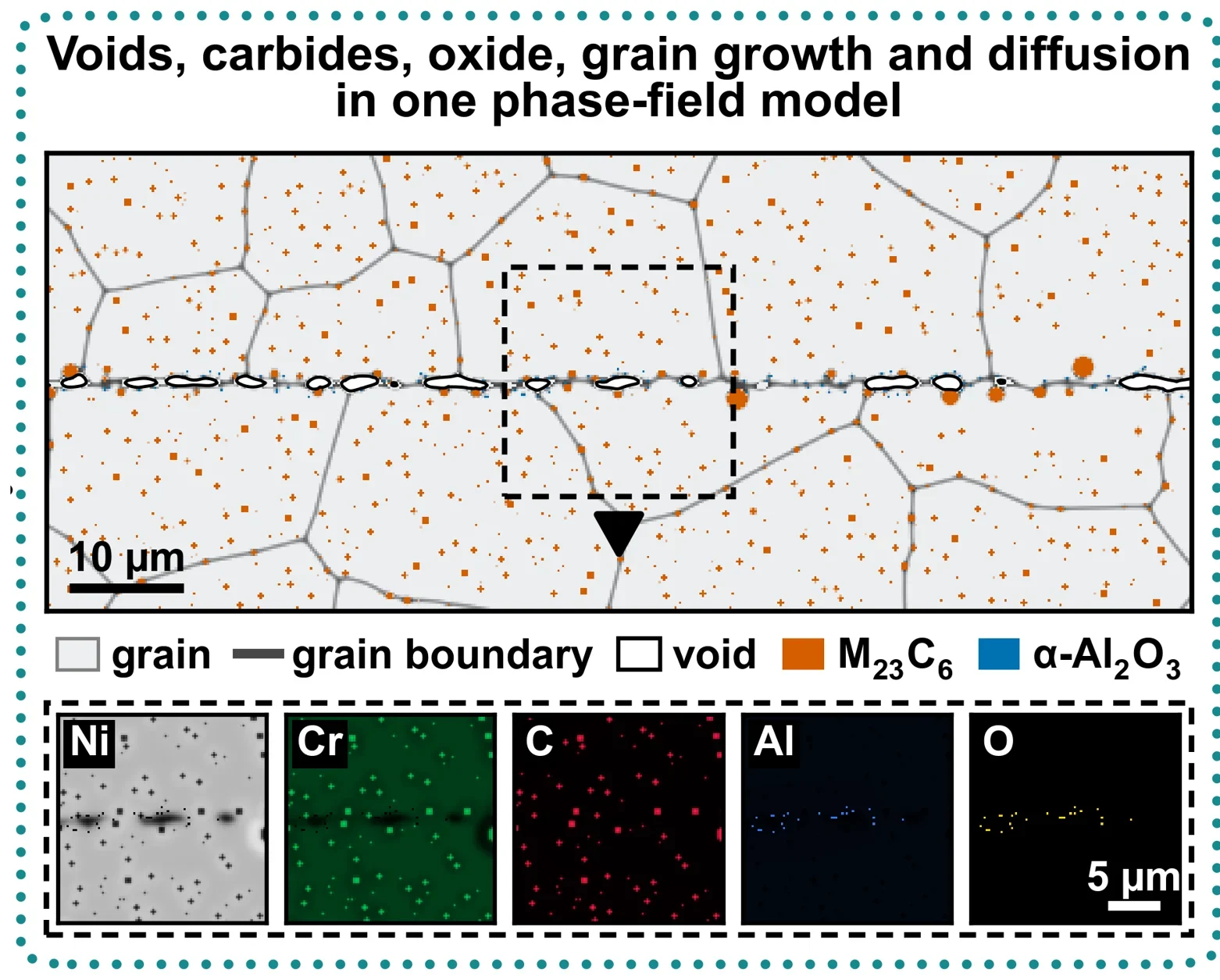
Simulated bond line with grains, voids, carbides, oxides and element maps
Voids, carbides, oxide, grain growth and diffusion in one model: the bond line at an intermediate time, with the simulated element distributions (Ni, Cr, C, Al, O) in the boxed region.
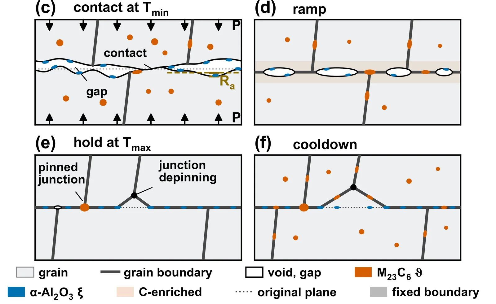
Schematic of the four bonding stages
Mechanisms resolved by the model: (c) rough contact under pressure, (d) voids and carbides during the ramp, (e) carbide pinning and boundary depinning during the hold, (f) the bond line after cooldown.
Large simulation before and after the hold
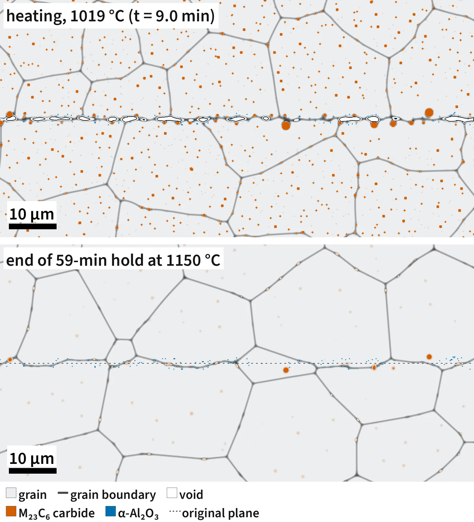
A 100 × 50 µm window of a 200 × 100 µm simulation. Top: during heating, with interface voids and carbides. Bottom: after a 59 min hold at 1150 °C, with grains grown across the original plane (dotted).

Model and code: R. Wang, F. Gao group, U. Michigan. DOE NEUP Integrated Research Project on diffusion bonding for compact heat exchangers. Manuscript in preparation.

Diffusion bonding of 316H stainless steel

The first version of the bonding model, developed for 316H stainless steel. It relates processing conditions (temperature, pressure, surface roughness) to void closure and grain morphology at the bond line, and to the resulting bonding ratio.

Own code In-house code, written from scratch in Fortran with MPI; no commercial software.
Bond line during bonding. Top: grains (grey boundaries) and interface voids (orange). Bottom: vacancy concentration around the shrinking voids.
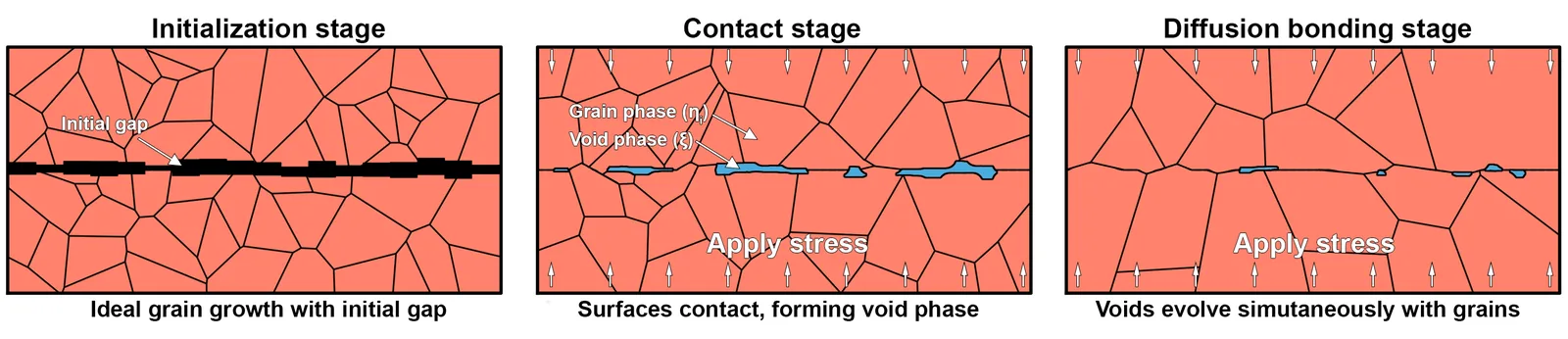
Schematic of the three modeling stages
Three modeling stages: initialization with an initial gap, surface contact under applied stress, and diffusion bonding with voids evolving together with the grains.
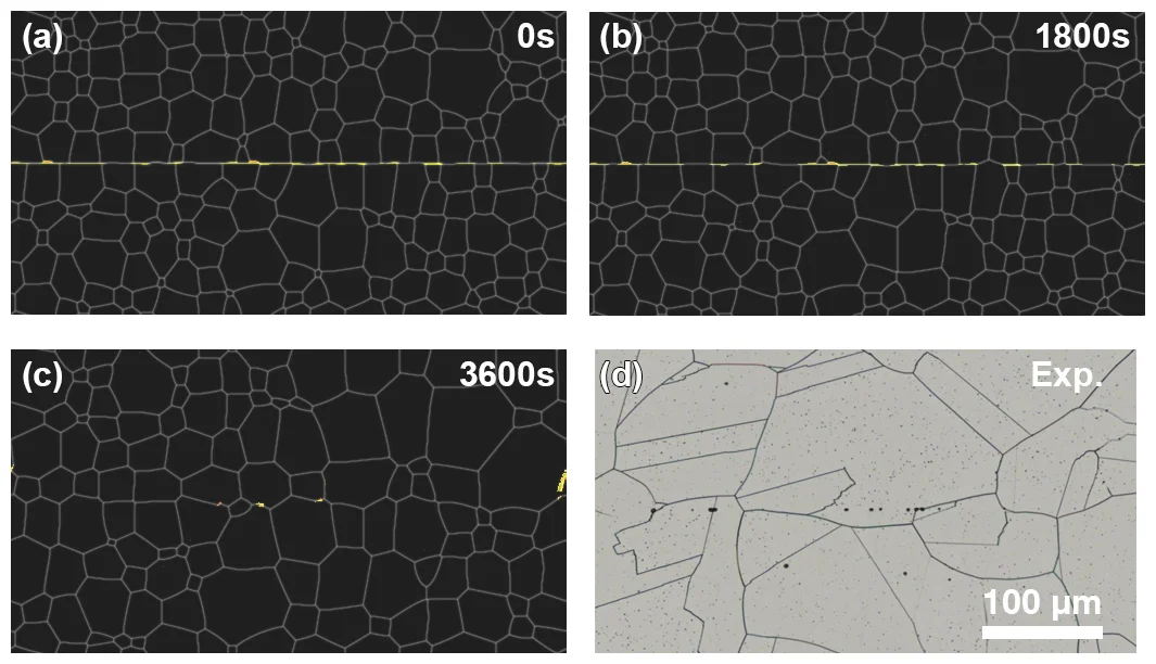
Simulated bond line over time next to an experimental micrograph
Model validation (1050 °C, 8 MPa, Ra = 0.1 µm): simulated bond line at 0, 1800 and 3600 s (a–c), compared with an optical micrograph of a bonded joint from the project (d). Mater. Sci. Eng. A 2025, Fig. 9.
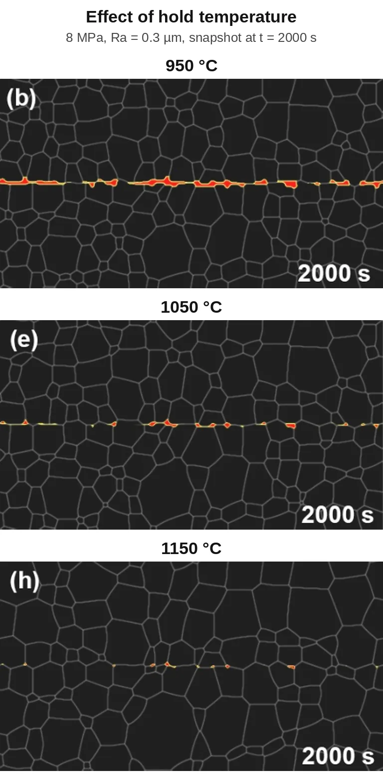
Bond line at three hold temperatures
Effect of hold temperature (950, 1050, 1150 °C; 8 MPa, Ra = 0.3 µm; t = 2000 s). Mater. Sci. Eng. A 2025, Fig. 12.
Bond line at three surface roughness values
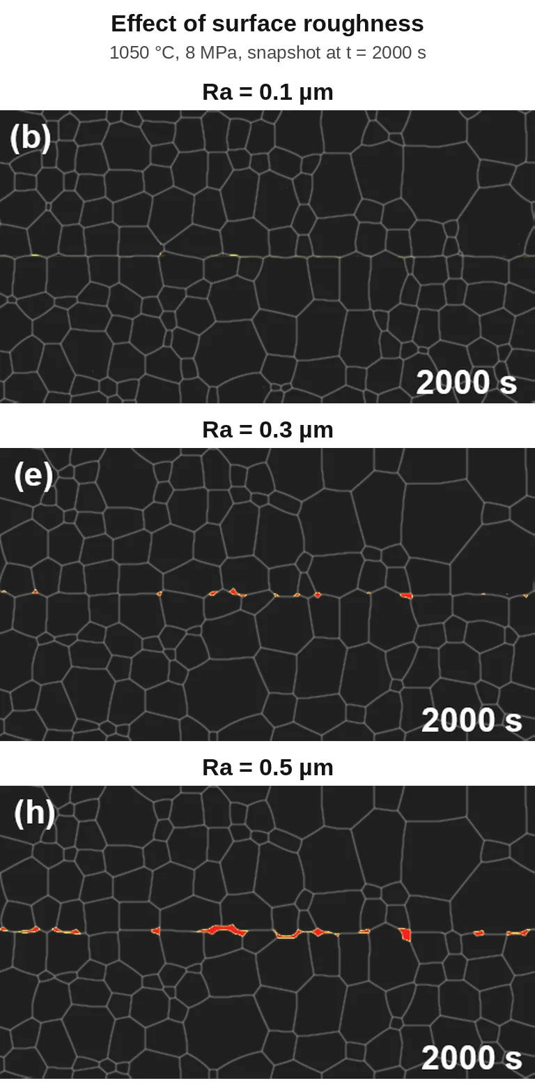
Effect of surface roughness (Ra = 0.1, 0.3, 0.5 µm; 1050 °C, 8 MPa; t = 2000 s). Fig. 14.
Bond line at three bonding pressures
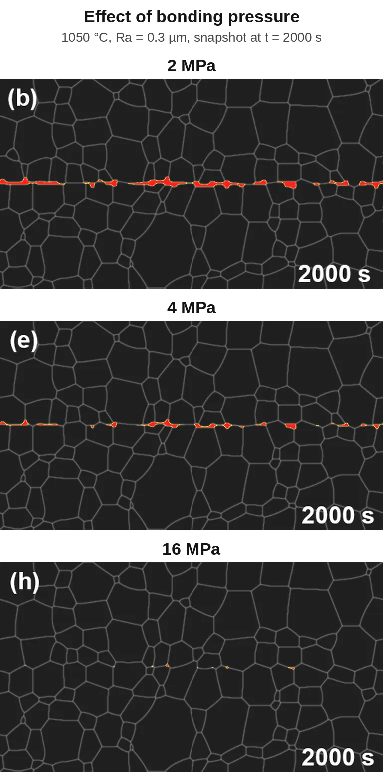
Effect of bonding pressure (2, 4, 16 MPa; 1050 °C, Ra = 0.3 µm; t = 2000 s). Fig. 16.

Papers: Mater. Sci. Eng. A 2025 · AM-EPRI 2024
Model and code: R. Wang, F. Gao group, U. Michigan, with Argonne National Laboratory.